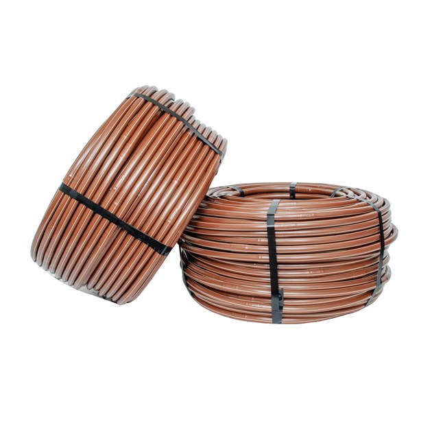
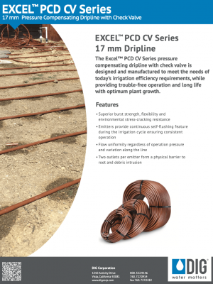
Excel™ PCD CV 17 mm Dripline with Check Valve
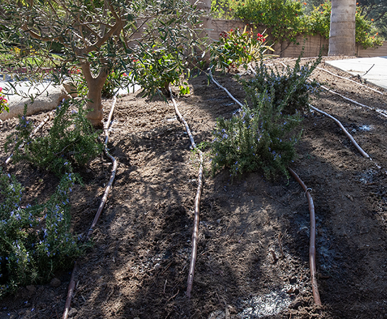
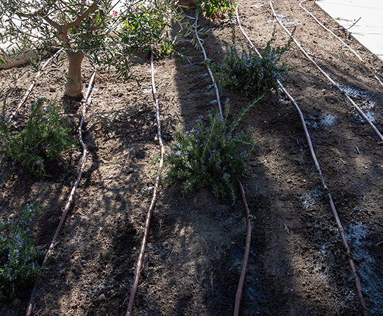
DIG’s Excel™ PCD CV Pressure Compensating Dual Outlet Dripline with Check Valve is a reliable, durable, and precise solution for subsurface irrigation, particularly suited for narrow or dense plantings. This advanced dripline features cylindrical drip emitters with built-in check valves that prevent siphoning when water pressure drops below 2.5 PSI. This anti-siphoning capability protects the emitters from sediment, soil particles, and debris entering the dripline, ensuring long-term reliability.
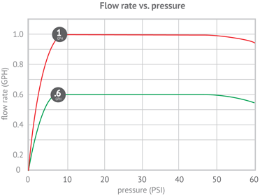
Each emitter is equipped with a floating diaphragm that regulates and maintains a consistent flow rate across a wide range of inlet pressures, from 12 to 50 PSI, making it ideal for demanding conditions. The Excel PCD CV Dripline also includes a colored stripe to indicate flow rate, simplifying identification and installation.
Unlike traditional driplines with a single outlet, the Excel PCD CV Dripline is designed with two outlets per emitter. This dual-outlet design provides redundancy; if one outlet becomes blocked, the opposing outlet continues to function, maintaining consistent performance.
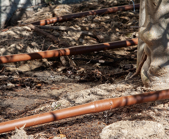
Constructed from premium low-density polyethylene resins with UV protection, the dripline combines robust environmental stress-cracking resistance and burst strength with its anti-siphoning capability, making it an ideal choice for subsurface irrigation applications. The durable, large cylindrical emitters ensure the system’s reliability and efficiency in various challenging environments.
Features:
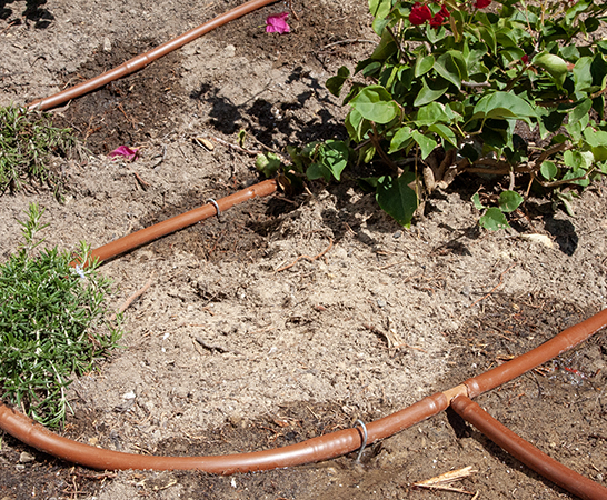
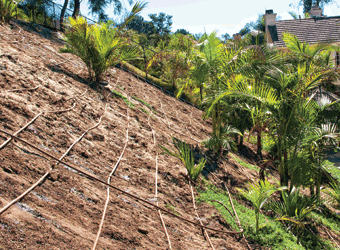
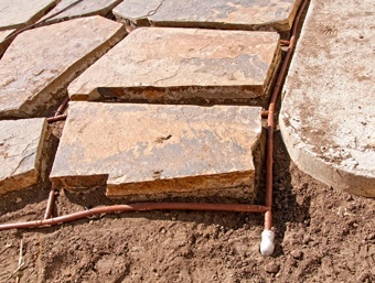
- Versatile Installation: Can be installed both above or below grade, offering flexibility in a variety of applications.
- Built-In Check Valves: Inline emitter check valves prevent drainage when water pressure drops below 2.5 PSI, safeguarding the emitters from siphoning small sediment and soil particles into the dripline.
- Dual Outlet Design: Each emitter features two outlets; if one becomes blocked, the second outlet on the opposite side ensures continued performance and reliability.
- Customizable Options: Available in two flow rates, with a wide range of emitter spacing and tubing lengths, allowing for maximum design flexibility to suit diverse irrigation needs.
- Color-Coded Identification: Dripline comes with double-striped color codes, representing different flow rates for easy identification.
- Pressure Compensating: Provides consistent flow uniformity across varying operating pressures and line lengths, ensuring efficient water distribution.
- Integrated Emitter Design: The drip emitter and diaphragm are self-contained units, molded directly into the interior wall of the tubing for enhanced durability and performance.
- Clog-Resistant Flow Path: The flow path design is optimized to resist clogging, with turbulent flow through large labyrinth water passages leading water into the flow control chamber.
- Self-Flushing Diaphragm: The floating silicone diaphragm within the flow control chamber regulates constant flow rates and allows for self-flushing, clearing debris that might bypass the inlet filter.
- Secondary Filtration: The intake inlet is equipped with raised grooves acting as a secondary filter, continuously flushing particles away from the labyrinth to enhance clogging resistance.
- Root and Debris Protection: The check valve, combined with dual oppositely oriented outlets, acts as a physical barrier against root intrusion and debris, maintaining system integrity.
- Chemical and UV Resistance: Resistant to the chemicals and fertilizers commonly used in landscaping and protected against UV degradation for long-lasting durability.
- Flexible and Easy to Install: The flexible tubing design facilitates easy installation, adapting to various layouts and environments.
- Clear Labeling: The dripline is printed with flow rate and size for easy identification during installation.
- Wide Compatibility: Designed for use with DIG’s 17 mm barb fittings, .670″ OD compression fittings, and universal NUTLOC™ fittings, ensuring compatibility with existing systems.
How to Specify
| MODEL | DESCRIPTION |
|---|---|
| 500 Feet | Excel™ Series 17 mm Pressure Compensating Dripline with Built-in Check Valve (CV) | |
| A5-512P-CV | .6 GPH (2.3 L/H), .670" OD 12 in. spacing |
| A5-518P-CV | .6 GPH (2.3 L/H), .670" OD 18 in. spacing |
| A1-512P-CV | 1 GPH (3.8 L/H), .670" OD 12 in. spacing |
| A1-518P-CV | 1 GPH (3.8 L/H), .670" OD 18 in. spacing |
| 1000 Feet | Excel™ Series 17 mm Pressure Compensating Dripline with Built-in Check Valve (CV) | |
| A5-12P-CV | .6 GPH (2.3 L/H), .670" OD 12 in. spacing |
| A5-18P-CV | .6 GPH (2.3 L/H), .670" OD 18 in. spacing |
| A1-12P-CV | 1 GPH (3.8 L/H), .670" OD 12 in. spacing |
| A1-18P-CV | 1 GPH (3.8 L/H), .670" OD 18 in. spacing |
| 250 Feet | Excel™ Series 17 mm Pressure Compensating Dripline with Built-in Check Valve (CV) | |
| A5-212P-CV | .6 GPH (2.3 L/H), .670" OD 12 in. spacing |
| A5-218P-CV | .6 GPH (2.3 L/H), .670" OD 18 in. spacing |
| A1-212P-CV | 1 GPH (3.8 L/H), .670" OD 12 in. spacing |
| A1-218P-CV | 1 GPH (3.8 L/H), .670" OD 18 in. spacing |
| 100 Feet | Excel™ Series 17 mm Pressure Compensating Dripline with Built-in Check Valve (CV) | |
| A5-112P-CV | .6 GPH (2.3 L/H), .670" OD 12 in. spacing |
| A5-118P-CV | .6 GPH (2.3 L/H), .670" OD 18 in. spacing |
| A1-112P-CV | 1 GPH (3.8 L/H), .670 od 12 in. spacing |
| A1-118P-CV | 1 GPH (3.8 L/H), .670" OD 18 in. spacing |
Specifications
- Flow rates:
- .6 GPH (2.3 L/H) drip emitter color code - orange
- Drip line double stripe code - beige
- 1 GPH (3.8 L/H) drip emitter color code - gray
- Drip line double stripe code - gray
- Operating pressure: 12-50 PSI (.8-3.5 BAR)
- Check valve sealing pressure: 2.5 PSI (.17 BAR)
- Check valve opening pressure: 4.3 PSI (.3 BAR)
- Materials: Dow FINGERPRINT™ DFDA-7510 NT linear low-density polyethylene resin with a minimum of 2% carbon black
- Dripline color: brown
- Size: 1/2" (.570" ID x .670" OD)(14.5 mm ID x 17 mm OD)
- Spacing: 12", 18" or 24" (30.5 cm, 45.7 cm and 61 cm)
- Available in 100', 250', 500' and 1000' coils (30 m, 75 m,150 m and 300 m)
- Minimum bending radius: 1' (.3 m)
- Filter requirement: minimum of 150 mesh
Maximum single lateral length Flow rate .6 GPH (2.3 L/H) DOUBLE STRIPE COLOR, BEIGE
| Dripper Spacing | 15 PSI (1.0 BAR) | 25 PSI (1.7 BAR) | 35 PSI (2.4 BAR) | 45 PSI (3.2 BAR) |
|---|---|---|---|---|
| 12" (30 m) | 215' (65 m) | 304' (92 m) | 343' (104 m) | 442' (134 m) |
| 18" (45 m) | 244' (74 m) | 406' (123 m) | 459' (139 m) | 548' (166 m) |
| 24" (60 m) | 370' (112 m) | 482' (146 m) | 617' (187 m) | 772' (234 m) |
Maximum single lateral length Flow rate 1.0 GPH (3.8 L/H) DOUBLE STRIPE COLOR, GRAY
| Dripper Spacing | 15 PSI (1.0 BAR) | 25 PSI (1.7 BAR) | 35 PSI (2.4 BAR) | 45 PSI (3.2 BAR) |
|---|---|---|---|---|
| 12" (30 m) | 145' (44 m) | 185' (56 m) | 248' (75 m) | 287' (87 m) |
| 18" (45 m) | 221' (67 m) | 294' (89 m) | 347' (105 m) | 413' (125 m) |
| 24" (60 m) | 294' (89 m) | 403' (122 m) | 479' (145 m) | 512' (155 m) |
Flow rate per 100 feet (30 M) (Flow rate 0.6 GPH)
| Dripper Spacing | Flow (GPM) | Flow (L/M) | Flow (GPH) | Flow (L/H) |
|---|---|---|---|---|
| 12" (30 cm) | 1.00 | 3.8 | 60 | 227 |
| 18" (45 cm) | 0.67 | 2.5 | 40 | 151 |
| 24" (60 cm) | 0.50 | 1.9 | 30 | 114 |
Flow rate per 100 feet (30 M) (Flow rate 1.0 GPH)
| Dripper Spacing | Flow (GPM) | Flow (L/M) | Flow (GPH) | Flow (L/H) |
|---|---|---|---|---|
| 12" (30 cm) | 1.67 | 6.3 | 100 | 379 |
| 18" (45 cm) | 1.11 | 4.2 | 66.7 | 252 |
| 24" (60 cm) | 0.83 | 3.2 | 50 | 189 |
CAD Files
-
17 mm Excel™ PC-CV Pressure Compensating Drip Line With Check Valve

-
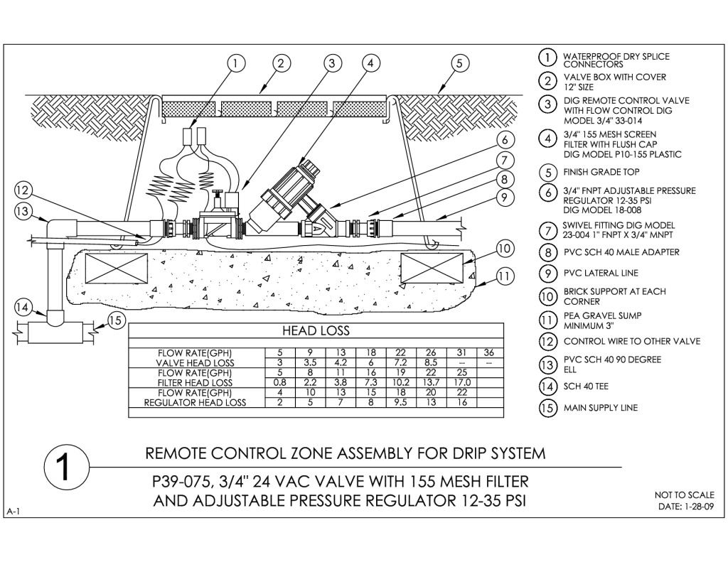
1
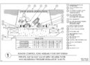
Remote Control Zone Assembly for Drip System P39-075
-
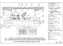
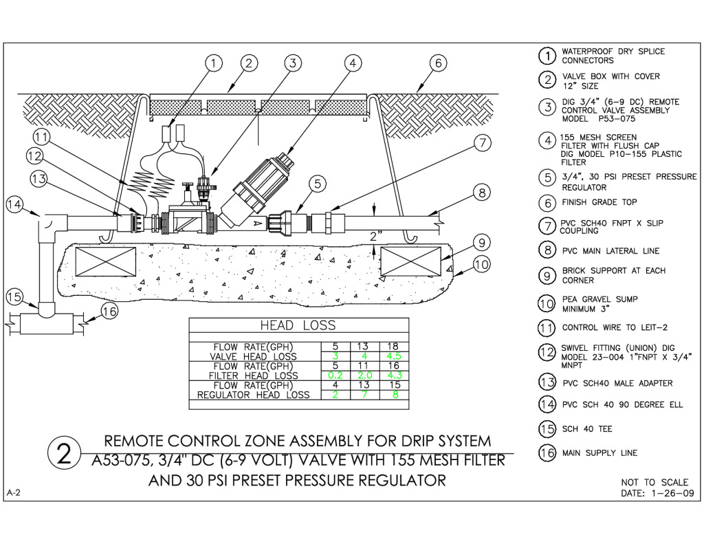
2
Remote Control Zone Assembly for Drip System A53-075
-
3
Excel™ drip line for subsurface installation, side view
-
4
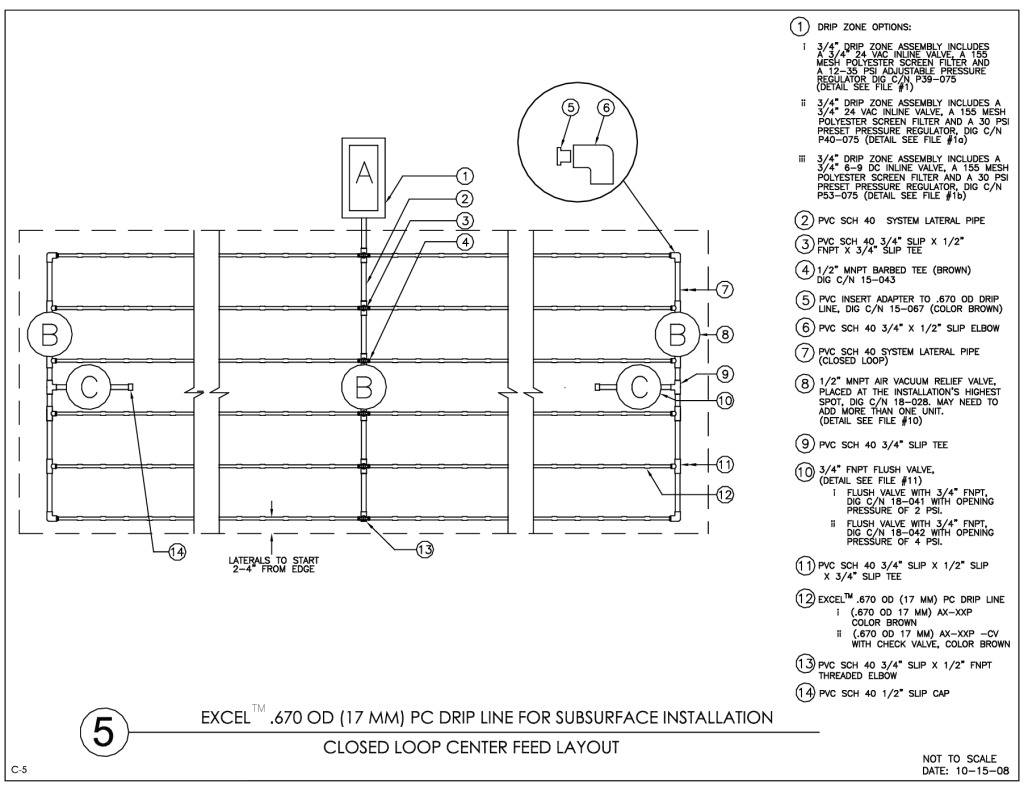
Excel™ drip line for subsurface installation, closed loop center feed layout
-
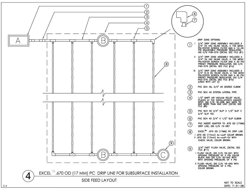
5
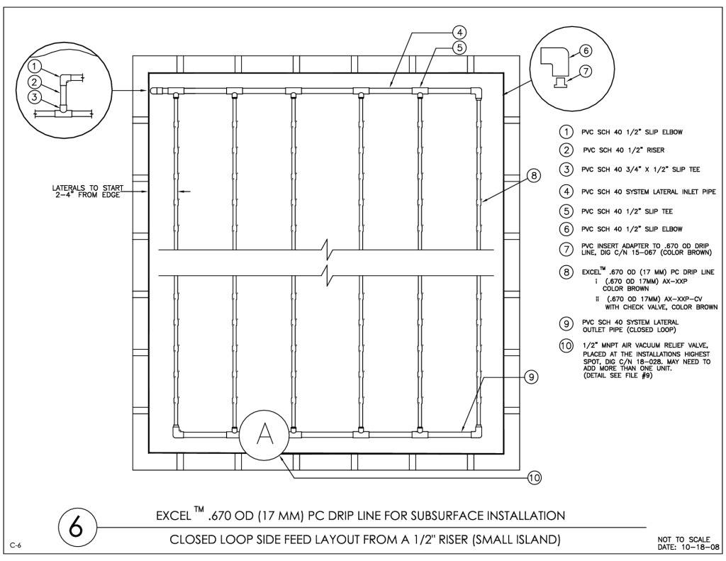
Excel™ drip line for subsurface installation, side feed layout from a 1/2" riser
-
6
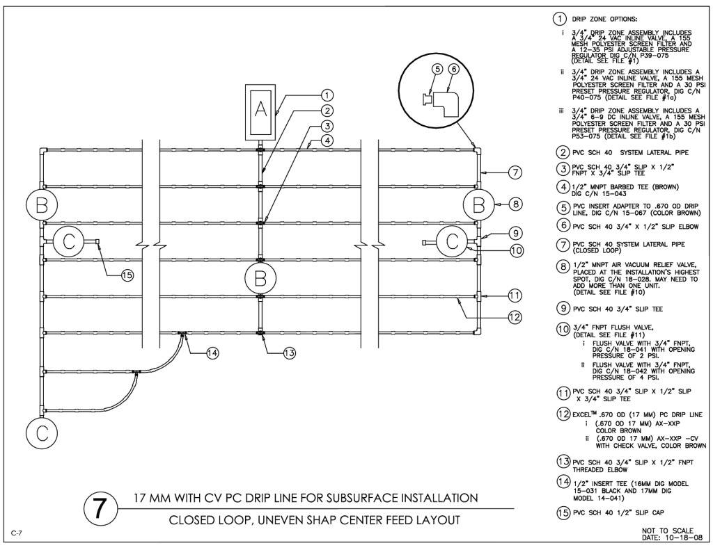
Excel™ drip line for subsurface installation, closed loop, uneven shape center feed layout
-
7
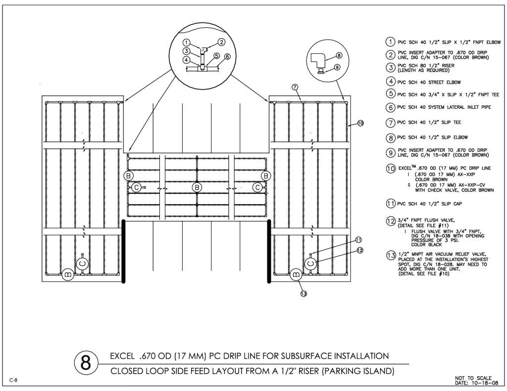
Excel™ line for subsurface installation, closed loop side feed layout from 1/2" riser (parking island)
-
8
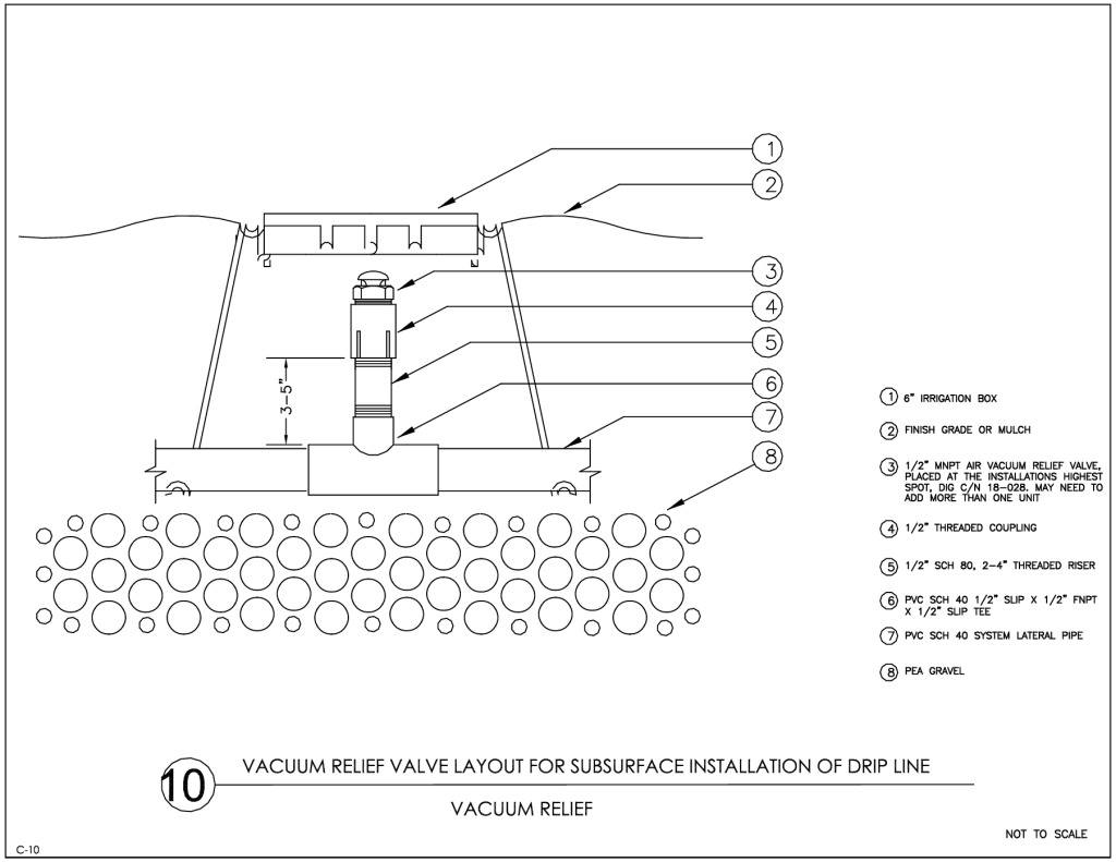
Vacuum relief valve layout for subsurface installation of drip line
-
9
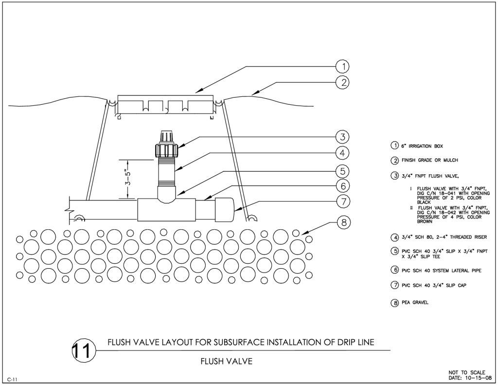
Flush valve layout for subsurface installation of drip line
-
1

 English
  Spanish